

Deep Dive 1: The Importance of CAD Conversion in Product Visualization
Why CAD files aren’t render-ready and how learning to convert them gives you an edge

In the previous article Start Here: Product Visualization for 3D Artists, I provided an overview of the booming field of product visualization for 3D artists. This week, we’re kicking off the first deep-dive article in the series and there’s no better place to start than with the OG of digital product models: CAD designs. The ability to convert CAD models for visualization is a cornerstone of product viz workflows. In this article, we’ll explore what CAD is (with a bit of history), why it’s so crucial in product design, and how mastering CAD conversion can help you stand out as a 3D artist in the product visualization industry.
As stated, this is part of a large ongoing process that I would love your insights on. So roll up your sleeves and jump in here with me.
What is CAD? A Quick History Lesson
CAD stands for Computer-Aided Design. It refers to the use of computers to assist in the creation, modification, analysis, or optimization of a design. Long before fancy real-time 3D renderers and game engines, engineers were already using CAD programs to draft precise technical drawings and 3D models of products.
 Definition | Arena")
But where did it all begin?
Early CAD development dates back to the 1950s and 60s, when pioneers like Ivan Sutherland introduced fundamental concepts with his Sketchpad system in 1963. Sketchpad was a revolutionary program that allowed designers to draw directly on a screen with a light pen, establishing the groundwork for interactive graphics in design software. By the late 1960s, other computing innovations (such as the graphical user interface and the mouse, demonstrated by Douglas Engelbart) set the stage for CAD software to enter mainstream engineering and design.
The 1970s and 1980s saw CAD technology rapidly advance and spread into industry. Initially, only large organizations (notably in automotive and aerospace) adopted CAD, mainly because it offered greater precision and speed compared to traditional paper drafting. Early CAD systems were often custom in-house programs tailored to a company’s needs. But this began to change with the introduction of more general-purpose CAD software. A pivotal moment was the release of AutoCAD in 1982, which exemplified the shift from specialized, expensive systems to more accessible drafting software. From that point onward, a wide range of industries (beyond just cars and airplanes) started using CAD in their product design process. CAD software also evolved from simple 2D drafting to full 3D modeling in this era, enabling engineers to create three-dimensional representations of parts and assemblies on-screen for the first time.
Fast forward to today, and CAD tools have become integral to product design and engineering. Modern CAD programs allow the creation of detailed 3D solid models complete with exact dimensions and properties.
In short, CAD isn’t just a high-tech replacement for drafting on paper; it augments the design process by enabling analysis, virtually unlimited iteration, and highly accurate virtual prototyping. These capabilities have dramatically sped up development cycles and reduced the need for costly physical prototypes in many industries. CAD truly revolutionized product design by making it faster, more precise, and more collaborative than the age of pencils and drafting tables.
CAD’s Role in Product Design (and Why It Matters for Visualization)
So why are we, as 3D artists, talking so much about CAD in the context of product visualization? It’s because CAD models are the source of truth for virtually every manufactured product. In product design and engineering, CAD files are the definitive digital representation of a product’s geometry. They contain every detail needed to manufacture the item…often down to each screw, wire, and tiny internal component. In other words, a CAD model isn’t just a pretty shell of the product’s exterior; it’s typically an all-encompassing digital twin of the product’s structure.
Traditionally, the primary purpose of CAD models is to communicate precise dimensional information to manufacturing. A mechanical engineer designing, say, a new smartphone or a car part will use CAD software to model that component with exact measurements and specifications. These CAD files then inform fabrication processes (like CNC machining, 3D printing, or injection molding) to actually produce the part. Because of this manufacturing focus, CAD models prioritize accuracy and completeness over visual polish. In an engineering context, it doesn’t matter how “pretty” the 3D model is. What matters is that every hole, fillet, and fitting is exactly in the right place.
For those coming from other 3D fields (like entertainment, gaming, or visual effects), it’s important to understand this fundamental difference. When you’re making models for film or games, you often optimize for visual impact and performance. You might omit unseen backfaces, use low-poly approximations, or take artistic liberties for aesthetics. Not so with CAD models. A CAD model of a product is meant to be an exact virtual replica. If the real product has an internal circuit board or a network of bolts and brackets, the CAD assembly likely includes every one of those hidden elements. All those tiny parts and details ensure that the product can be manufactured correctly and assembled in the real world.

Another key difference is that CAD software operates with NURBS surfaces or mathematically defined solids, rather than the polygonal meshes we’re used to in DCC (Digital Content Creation) tools like Blender or Maya. CAD geometry is highly precise and can be infinitely smooth, whereas visualization typically uses polygons/pixels which approximate that geometry. CAD programs usually don’t concern themselves with things like UV maps for texturing, or optimal polygon counts – those concepts are mostly irrelevant in an engineering context.
Now, from a product visualization standpoint, this rich, highly accurate CAD data is both a blessing and a curse. On one hand, if a company has already designed a product in CAD, you theoretically have a ready-made 3D model to work with for creating marketing visuals, animations, and renderings of that product. No need to model it from scratch – in theory, you can take the CAD data and render beautiful images or turntables of the product. This is the ideal scenario companies dream of: one 3D asset pipeline that goes from design to manufacturing to marketing. In practice, however, it’s not so straightforward. This is where CAD conversion comes in (and where you, the 3D artist, can add a ton of value).
From CAD to Beautiful Renders: The Challenge of CAD Conversion
If CAD models contain all this great detail, why can’t we just drop a CAD file into our favorite rendering software and hit “render”? The short answer: CAD models are not optimized for visualization workflows. Converting a CAD model into a format suitable for high-quality rendering or real-time visualization is often a tricky, time-consuming process. Anyone who’s tried to import a raw CAD file (like a STEP or IGES from SolidWorks, Creo, or CATIA) into a tool like Blender, Maya, or even Adobe’s Substance 3D Stager can attest that the results aren’t always pretty.

CAD data typically needs to be tessellated (converted from mathematical surfaces into polygons) for use in most rendering or game engines. During this conversion, a lot can go wrong. Here are some of the common issues that arise when converting CAD models into polygonal 3D models for visualization:
Excessively High Poly Count: A straightforward CAD-to-mesh conversion often produces an insanely dense mesh. The software tessellates every curved surface into thousands of tiny triangles to approximate the smooth CAD geometry. The result can be millions of polygons for even moderately complex objects, making the file heavy and unwieldy (sometimes so large it crashes the DCC tool). This happens because CAD models capture tiny details and exact curves that, when blindly converted, turn into an overwhelming number of facets. High polygon counts not only slow down your workflow but also may be unnecessary for visualization (e.g., internal components or hidden features that won’t even be seen in the render).
Missing Fillets and Fine Details: Paradoxically, while CAD models are very detailed, they sometimes omit tiny cosmetic fillets or bevels on edges (especially if those don’t affect fit or function). Many CAD designs have perfectly sharp edges which, in reality, would be slightly rounded for manufacturing or aesthetic reasons. For a photorealistic render, you often need to add those bevels back in, otherwise the CG render looks unnaturally sharp. So part of the “conversion” process might involve sculpting or adjusting geometry to introduce small chamfers, curved corners, and other details to make the model look realistic under lights.
Flipped Normals: The way CAD stores surface orientation doesn’t always translate well into polygon normals. It’s common to import a CAD model and find that some faces are inside-out (normals inverted) or inconsistent. This results in weird shading artifacts or even invisible geometry (if backface culling is on). Fixing this can require manually selecting faces and flipping normals, or recomputing them, which is a tedious process if the model has thousands of separate surfaces.

What Flipped Normals look like in Maya Holes and Missing Faces: Tessellation algorithms can sometimes produce holes or gaps in the mesh. For instance, a surface that was continuous in CAD might come in as a non-water-tight set of polygons with missing facets (especially if the CAD file had very thin walls or complex boolean cuts). These open faces not only cause rendering issues but can also disrupt features such as ambient occlusion or physics simulations in real-time use. The 3D Artist often has to patch these holes manually (or with specialized tools) to create a solid, watertight model.
Broken Apart Meshes: Another conversion quirk is that a single logical part might import as many disjointed pieces. For example, a staircase model might come through not as one continuous mesh, but as a collection of many separate planar surfaces that originally formed each step. All those pieces then need to be welded or merged back together to behave like a unified object in a visualization context. This is a time-consuming step, requiring you to identify which fragments belong together and reconnecting them.
No UVs (or Bad UVs): In Product Viz, artists rely on UV mapping to apply textures and materials correctly. CAD models don’t have UV coordinates in the way polygon models do. They’re usually un-textured or use procedural materials. When you convert to a mesh, you often end up with either no UVs at all or an automatically generated UV that is essentially useless (stretched, overlapping, or fragmented). This means you’ll likely have to unwrap UVs from scratch on the imported model if you plan to do any texture painting or decal application. For complex assemblies, unwrapping UVs can be a huge task in itself.

In short, while CAD data gives you a head start by providing the base geometry, it doesn’t come in “render-ready.” A senior 3D artist once jokingly told me about his “one-click solution” to CAD conversion: press the delete key, toss the CAD model, and model the whole thing from scratch using the CAD drawings as reference. His joke underscores a truth: converting CAD to a clean polygonal model can be so painful that sometimes rebuilding it manually can actually be faster.
Strategies for Smoother CAD Conversion
Reading the above, you might wonder if converting CAD is worth the trouble. Take heart; it can absolutely be done, and there are tools and techniques to make it easier. The industry is well aware of the CAD-to-visualization pipeline problem, and several solutions exist (albeit not yet a perfect magic bullet).
Some modern software tools are trying to bridge the gap by directly importing CAD formats and automating some of the cleanup. For example, Adobe’s Substance 3D Stager, Autodesk 3ds Max, Blender (with certain add-ons), and others can import common CAD file formats (STEP, IGES, etc.) and will perform initial tessellation. There are also specialized utilities and plugins (e.g., Okino PolyTrans, SimLab, Meshmatic, PiXYZ) designed to optimize CAD data for visualization. These can auto-weld vertices, adjust normals, remove hidden/internal parts, generate basic UVs, and even decimate the mesh to a more reasonable poly count. Depending on the complexity of the model and the specific software, such tools might save you a ton of manual labor.

However, even with these, expect to do some manual touch-ups. It’s wise to develop a workflow for yourself or your team to handle CAD imports. A typical workflow might look like:
Obtain the source CAD data. This could mean you export a neutral format (STEP, FBX, OBJ, etc.) from the CAD software.
Import into a cleanup tool or DCC software. Bring the CAD model into your 3D software of choice, or a specialized converter, and apply initial settings (tessellation quality, etc.). Sometimes you have control over tessellation density – you might choose a lower detail to reduce poly count, but be careful not to lose visibly important curves.
Organize and simplify. Once imported, organize the model hierarchy (group parts logically), delete any truly unnecessary internal components (for example, tiny screws inside that will never be visible in marketing visuals). Be cautious here: remove only what you are certain won’t be needed for the render or animation angles.
Fix geometry issues. Go through and weld vertices or join meshes where needed to make parts whole. Flip any inverted normals so that all faces render correctly. Fill holes by creating new polygons or using bridging tools. If certain small features caused messy topology, consider remodeling that part with clean geometry (for instance, extremely high-density bolts could be replaced with low-poly versions, etc.).
Add detail where needed. As noted, you may want to add small bevels or refine edges so they catch light realistically. Some rendering engines have tricks like shader-based rounded edges (e.g., Arnold’s round-corner shader), that can fake fillets without adding geometry, which is useful in many cases.

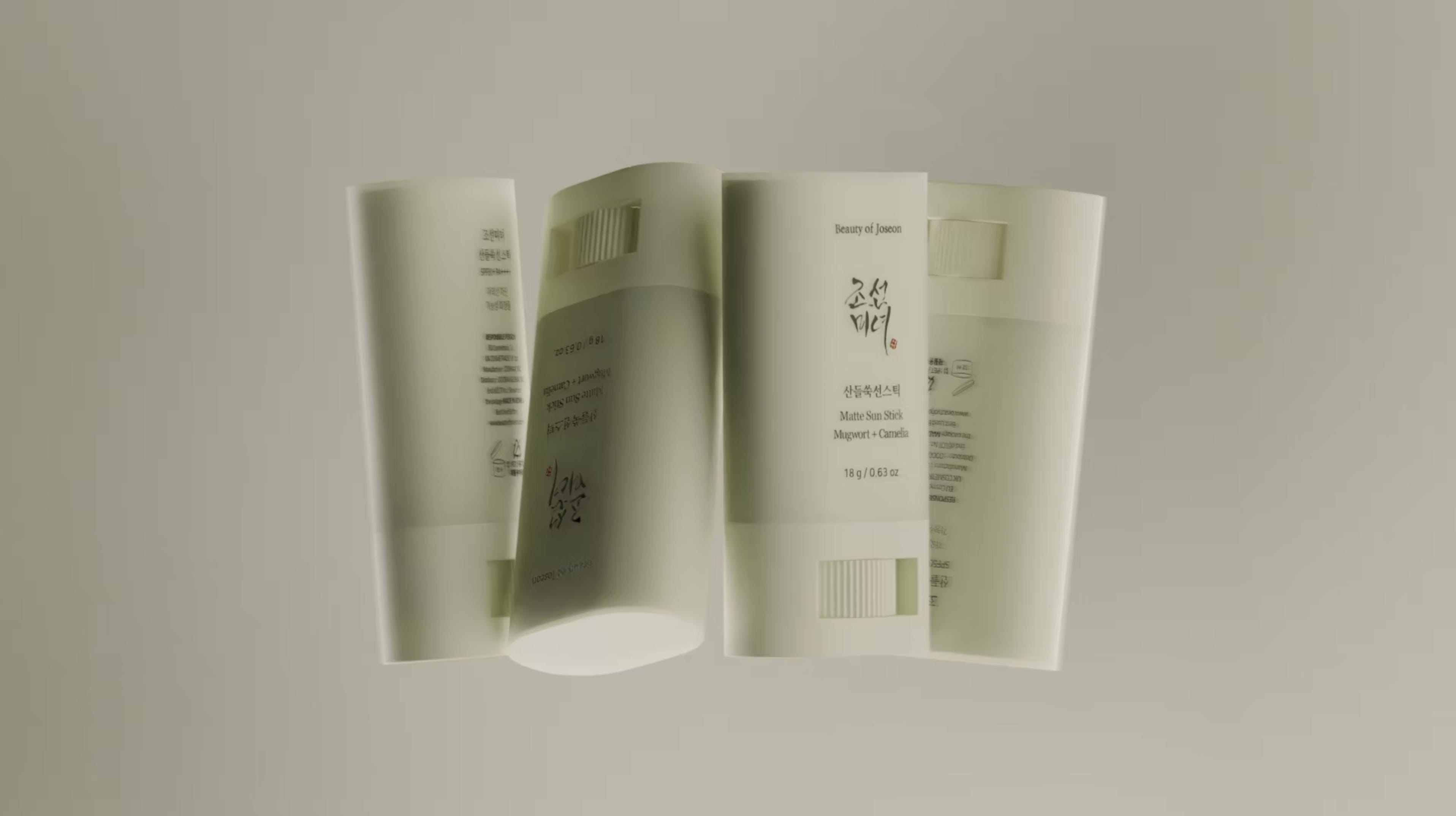
by Lukas Lejnar - https://www.lejnar.com/work/sunstick?pgid=lwnvu3cc-023337_2790fb8a58be4e79a145b996f969524emv2.jpg UV unwrap (if texturing is required). If your visualization will use image-based textures or decals, generate UV maps for the model. For simpler needs (like applying uniform materials or colors), procedural mapping might suffice, but anything involving logos or complex materials will need proper UVs.
Material and lighting setup. Now the model is ready for assigning materials, setting up lights, and doing the fun part – making it look awesome in renders!
The above process is not trivial. It takes time and technical know-how. But mastering this CAD conversion workflow is tremendously valuable. Many product companies today have a backlog of CAD files (since they use them for manufacturing), and they would love to repurpose them for things like marketing imagery, AR/VR experiences, or interactive web 3D viewers. The bottleneck is often finding someone who can take those CAD files and make them visually presentable. That’s where you can shine.
Why Mastering CAD Conversion Sets You Apart
Product visualization is a booming area, and companies are eagerly looking for talent who can bring their products to life digitally. If you’re a 3D artist transitioning from VFX, games, or another field, highlighting CAD conversion skills can be a major point of distinction for you.
Think about it from the employer’s perspective: They might have a stack of candidates who are great at modeling, texturing, and rendering, but few of them know anything about CAD or how to handle engineering data. If you can come in and say, “No problem. I can take your engineering team’s CAD models and quickly turn them into high-quality, lightweight assets for marketing or visualization,” that’s a huge value-add. You’re solving a headache that many companies don’t have the time or knowledge to solve internally.
In fact, demonstrating this skill can be as straightforward as adding one or two examples to your portfolio. For instance, you could take an existing CAD model (there are libraries of free CAD models on the web, like GrabCAD), convert and polish it, then showcase a before-and-after on your ArtStation or website. Label it clearly as a CAD conversion project by showing a screenshot of the raw imported CAD (maybe with faceted geometry and all) next to your final clean render. This communicates to potential employers, “I speak your language. I understand the data you already have, and I can work with it.”

In many cases, companies embarking on product visualization want a turn-key solution. They might think, “We have the CAD files from R&D; if only we could get nice images and animations out of them for marketing.” As a visualization specialist, you can be the one to offer that end-to-end solution: from CAD to captivating visuals. This not only saves them money (by reusing existing data and reducing the need for extra prototypes or photoshoots), but it also speeds up their pipeline. For example, using 3D renders means marketing can start before the physical product even exists, and any design change in CAD can quickly propagate to updated visuals.
Finally, keeping an eye on the future: the industry is continually moving toward tighter integration between design and visualization. Concepts like digital twins and real-time product configurators rely on having good 3D representations of products, often derived from the CAD source. By honing your ability to manage CAD data now, you’re preparing yourself for the next generation of tools and workflows (perhaps one day truly there will be that magical “one-click” CAD-to-beautiful-render button. And when it comes, you’ll be the expert ready to leverage it).
Conclusion
CAD models may be the “original” 3D models of products, but without skilled conversion they’re like uncut gems – full of potential, yet rough around the edges. For 3D artists aiming to break into product visualization, understanding how to take those precise, complex CAD designs and transform them into polished visuals is critical. It’s often the first step in a product viz pipeline and arguably the most important one to get right.
Mastering CAD conversion not only unlocks a wealth of existing 3D data at your fingertips, but it also makes you incredibly valuable to employers. You become the bridge between two worlds – engineering and visualization – speaking the language of both accurate design and aesthetic presentation. So embrace the challenge: learn the tools, practice on real CAD files, and add this powerhouse skill to your arsenal. It could very well be the key that unlocks your first big opportunity in the product visualization space, and set you apart as a versatile 3D artist who can truly do it all.
The 3D Artist Community

We are pumped to have the great Stephy Fung joining the 3DAC for an AMA this week!
Stephy Fung is a fashion artist and designer based in London, celebrated for blending her cultural heritage with contemporary streetwear aesthetics. A self-taught creative, she began her career in motion design before transitioning into digital fashion, developing expertise in tools like CLO3D, Cinema 4D, and Substance Painter. Her breakthrough came with the creation of one of the first digital qipaos, a modern reinterpretation of the traditional Chinese garment, which quickly gained attention and earned her a spot on Forbes Europe’s 30 Under 30 list in Art & Culture in 2024.
Fung has collaborated with global brands including Gucci, Xbox, Snapchat, Jo Malone, and Dell, pushing the boundaries of digital fashion and immersive storytelling. Alongside her client work, she shares her knowledge through tutorials, workshops, and livestreams, inspiring aspiring designers to explore 3D without traditional barriers. Her projects often merge personal narrative with technological innovation, positioning her as a leading voice shaping the future of digital fashion.
3D Merch is here and we have a new hoodie!

3D News of the Week
Modo is Not Going Open Source - LinkedIn
Download the DPC for Fashion Roadmap - The Interline
Unilever Enhances Product Imagery Production With Digital Twins - NVIDIA
Blender 5.0 to Feature Built-In ACES 2.0 View Transform - 80.lv
How AI-Driven Product Visualization is Accelerating the E-commerce Design Process - Imagine.io
Standardized Displacement in Unreal - YouTube
3D Tutorial

3D Job Spreadsheet
Link to Google Doc With A TON of Jobs in Animation (not operated by me)
Hello! Michael Tanzillo here. I am the Head of Technical Artists with the Substance 3D team at Adobe. Previously, I was a Senior Artist on animated films at Blue Sky Studios/Disney with credits including three Ice Age movies, two Rios, Peanuts, Ferdinand, Spies in Disguise, and Epic.
In addition to his work as an artist, I am the Co-Author of the book Lighting for Animation: The Visual Art of Storytelling and the Co-Founder of The Academy of Animated Art, an online school that has helped hundreds of artists around the world begin careers in Animation, Visual Effects, and Digital Imaging. I also created The 3D Artist Community on Skool and this newsletter.
www.michaeltanzillo.com
Free 3D Tutorials on the Michael Tanzillo YouTube Channel
Thanks for reading The 3D Artist! Subscribe for free to receive new posts and support my work. All views and opinions are my own!